7 Segment displays and the
new very small Max7219 drivers...
published september 2024
updated 22/9/2024 - new download links and video
7-segment displays are used a lot in simulators. For example, radios, altimeters, autopilots and a lot of other information can be displayed on them.
Different examples with different number of digits are shown on the right side. These are actually 7 LEDs, and when lighted in combination, they will show a number on the display. Actually there are 8 LEDs, there is one extra to display the decimal sign.
To get them working, you will need a specific driver for the kind of displays you have and also specific for the simulator software you are using to build your sim. So before buying them, you should inform which drivers are needed to work with your sim software.
So before buying them, you should inform which drivers are needed to work with your sim software.Types of 7 segment displaysI only handle the LED types, not the LCD and OLED screens. 7-segment displays are sold in different colors and different sizes. The ones we are showing here are common cathode types, and the color is amber. The available colors are red, blue, white, green, orange, and amber. The same is available as a common anode. A different type of connection requires a different type of driver and connection.

Types of 7 segment displays
I will only handle the LED type displays, not the LCD and OLED screens.
7-segment displays are sold in different colors and different sizes. The ones I am showing here are common cathode types, and they are available in red, blue, white, green, orange, and amber. The same is available as a common anode. A different type of connection requires a different type of driver and connection.
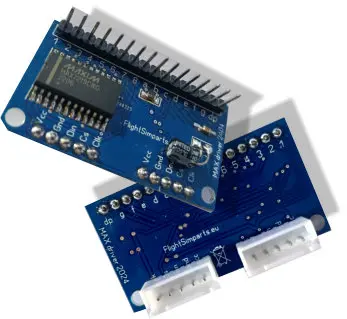
MAX7219 display with 8 digits
On the left I show you my MAX7219 boards, these are units that drives eight digits with one integrated circuit. It has current control and can even be dimmed via PWM. Again, you need to check if your SIM software can talk to these.
The ones on the left are my own design, a little bit more expensive than the Chinese ones. I made these because a lot of Chinese Max7219 units have problems. You don't pay much for the Chinese MAX7219 units, but what you get is certainly not quality.
Max7219 a working example
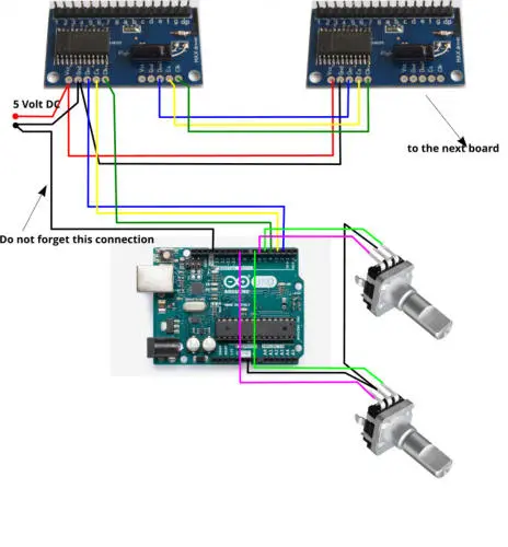
Below is the schematic diagram as an example of how to connect two Max7219 units to displays the frequencies of a radio.
Used are 2 Max drivers, 1 Arduino UNO, 2 encoders and 2 times 6 digit boards.
This example is a full set to construct a COM radio and display the frequencies or change them. It is based on X Plane with AirManager and Mobiflight. I have made a test with both programs.
If you are using MSFS or other simulators, you just have to change the simulator in Mobiflight and the link to the COM radio.
Below you can download the AirManager script to get everything working. AirManager is a product of https://siminnovations.com/.
There is also a very helpfull forum
AirManager script available for download
Arduino test script for MAX7219
Working example with my own designed Max7219
This example works with only 3 ports on an Arduino. The data that you see on the displays is static data from the programming file, just by means of an example to show what is possible.

Below a short video with a demo made with Mobiflight. In the video I show you a COM radio connected to XPlane via Mobiflight. Enjoy watching