Having a nice Main Instrument Panel without connection to the flight simulator is not big fun. A flight deck needs flickering lights, sounds, working instruments and so on. So what is involved in getting this panel to communicate, sent commands to the simulator, and receive data from the simulator. This article is about how this simulator is built, of course there other possibilities.
X-Plane 12 is our flight simulator which runs our aircraft, I'm using ZIBO mod 737NG, a Boeing 737NG modification made by Nico Dubruyn. It is important that you make this choices in the early stages of planning because you need to be sure that all parts, hardware, software, can be connected to each other. Indeed this is not an easy task and requires a lot of research and reading on forums for flightsim builders. And yet there are so many options as there are opinions. All the parts need to talk to each other, big task. With other words everything in this simulator must be adapted to work with X-Plane 12.
Communication with X-Plane is always done via Ethernet and the UDP protocol. Never mind about the UDP protocol, it's a way of sending signals over the network. Other parts of the simulator can receive and send information back and forth. A lot of simulators use USB cards, like Pokeys cards, to connect all the switches and lights. This is just another way to do things. Keep in mind that Ethernet is more stable than, for example, 25 USB cards that have to work together.
There are several techniques that you should master, or making yourself comfortable with. The most important one is basic electronics knowledge and soldering technic.
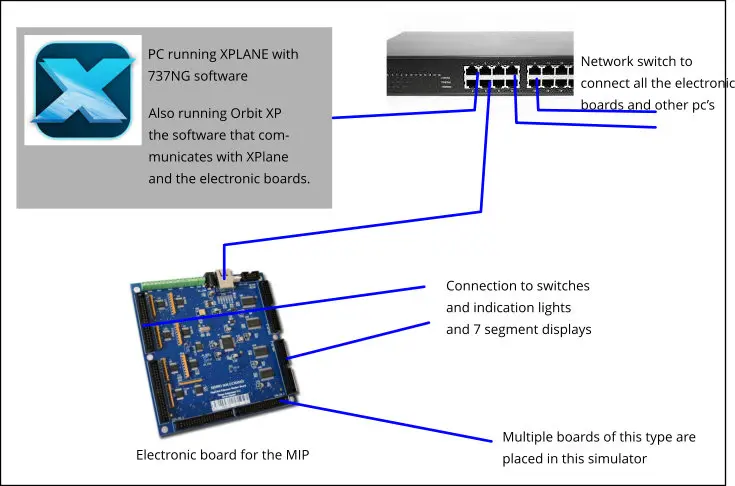
This simple connection diagram makes it clear that several components need to work together. When, for example, a switch is moved on the instrument panel, that signal goes to the "Electronic board" from where it goes to the switch and transfers to the network. "OrbitXP", which is always running together with X-Plane, says, Oh, there is a switch that changes state. I need to tell this to the simulator, X-Plane. Following this, the same switch in the simulator on the PC will be put in exactly the same state as it is on the physical instrument panel.
All this is very complex programming to synchronize the running simulator on the PC with the actual switches and warning lights in the cockpit, which is done by the programs you use. In this setup you do not need to worry about writing scripts or Arduino programming.
In this setup there are a multitude of "Electronic Motherboards", one for each bigger part of the simulator. So one for the MIP, the pedestal, the overhead panel, the MCP and EFIS blocks... There are also other cards involved that communciate with the "Motherboard", for example the "Servo" board or an extra input board. By doing it this way, it is easy to manage.
The manufacturer of the boards I'm using made it easy with lists of where each switch, light and display needs to be connected. If you follow this, everything should be working.
All the simulator programs that work together are very complex programming systems that synchronize the running simulator on the PC with the actual switches and warning lights in the cockpit. In this setup you do not need to worry about writing scripts, are Arduino programming. Just follow the list.
This is just the beginning article of how the sim works. Stay tuned and I will tell you more in other articles.
How is the Main Instrument Panel going to talk to X-Plane 12