Every microcontroller has some limitation on the maximum number of LED's you can connect to it. Arduino has it, Raspberry Pi has it, Pokeys cards have it.
Running more LED's than allowed will damage the microcontroller in a way that it will be unusable.
These boards will protect the microcontroller and are placed between the output port of the microcontroller and the LED's. The only purpose, give light to a series of LED's when the port is activated in a way up to 300mA per port. Not a single Arduino can run 300mA LED's. No supplementary programming is needed.
These boards can handle 24 separate outputs.
"Common anode" or "common cathode ??
This is the difference in how the LED's are connected. Anodes or cathodes connected together will tell you which board you need.
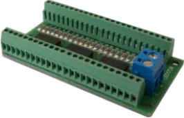 LED BOARD WITH SCREW CONNECTORS
WHAT DO YOU NEED? COMMON CATHODE OR COMMON ANODE
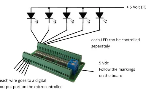
Both boards have different chips and are differently powered. In the common anode example, the positive lead of the power supply goes to the LEDs.
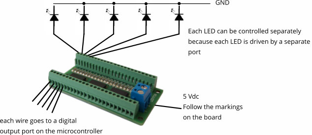
With the common cathode version, the LEDs are joined to the negative or GND of the power supply. If you need to connect led’s which you will wire yourself, it does’nt matter which version you use.
If you have a annunciator or panel from a supplier where you have to connect the LEDs, then it is important to know if the LEDs on the board are wired “Common Anode” or “Common Cathode”.
If you need one, I can help you with the board you need. Just sent me a message or mail me.
We value your opinion on this page and would love to hear from you.
Write us a short message on the bottom of this page in the field "Write a message".
Thanks
WIRING A COMMON CATHODE BOARD
WIRING A COMMON ANODE BOARD
Driving led's with a LED board